

 Integrated Magnetic Power Module
Buck (Step-Down)-Low Voltage
Buck (Step-Down)-Medium Voltage
Boost (Step-Up)
DC-DC Power Modules
Integrated Magnetic Power Module
Buck (Step-Down)-Low Voltage
Buck (Step-Down)-Medium Voltage
Boost (Step-Up)
DC-DC Power Modules
 Magnetically Integrated Power Module (SiP)
Buck (Step-Down)-Multiple Outputs
Buck (Step-Down)
Boost (Step-Up)
Magnetically Integrated Power Module (SiP)
Buck (Step-Down)-Multiple Outputs
Buck (Step-Down)
Boost (Step-Up)
 Customized DC-DC Converters
Tailored Power Modules: Precision Solutions for Your Unique Needs.
Contact Us Today to Discuss Your Project!
DC-DC Power Modules
Customized DC-DC Converters Explore DC-DC Converters
UDM22006 DC DC Integrated Magnetic Power Module ( Input 2.3V–5.5V, output 1.2V-3.3V )
Details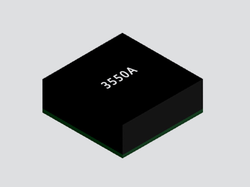
FHT3550 DC/DC Adjustable Buck Power Module ( 3.5V-40V Input, 1.0V-12.0V Output )
Details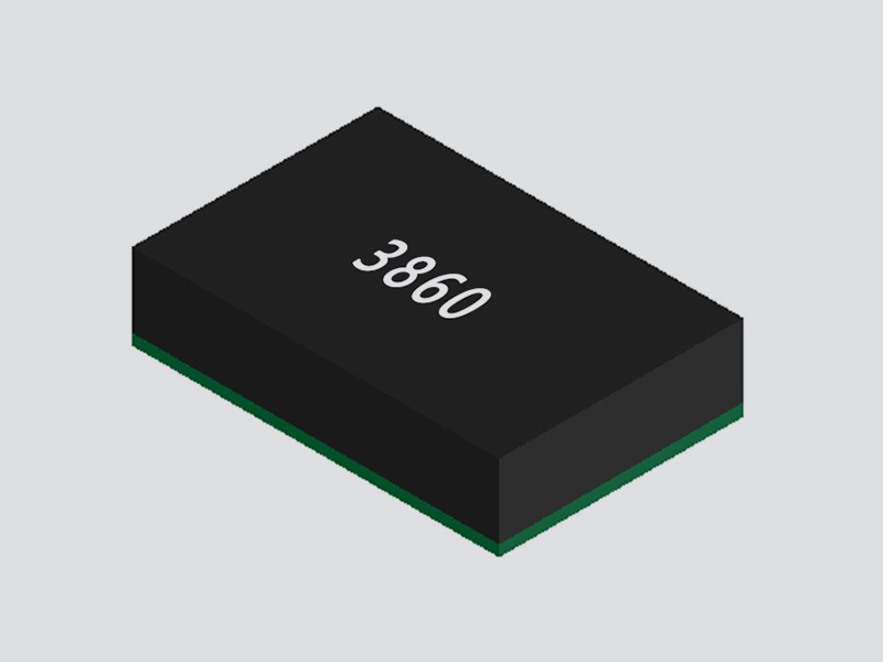
FHT3860 DC/DC Step-Down Buck Power Module ( 2.3V-5.5V Input, 0.5V-3.3V Output )
Details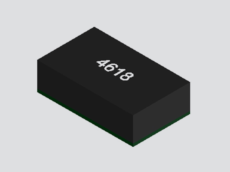
FHT4618 Integrated DC/DC Adjustable Buck Power Module ( 4.5V-24V Input, 0.6V-5.5V Output )
Details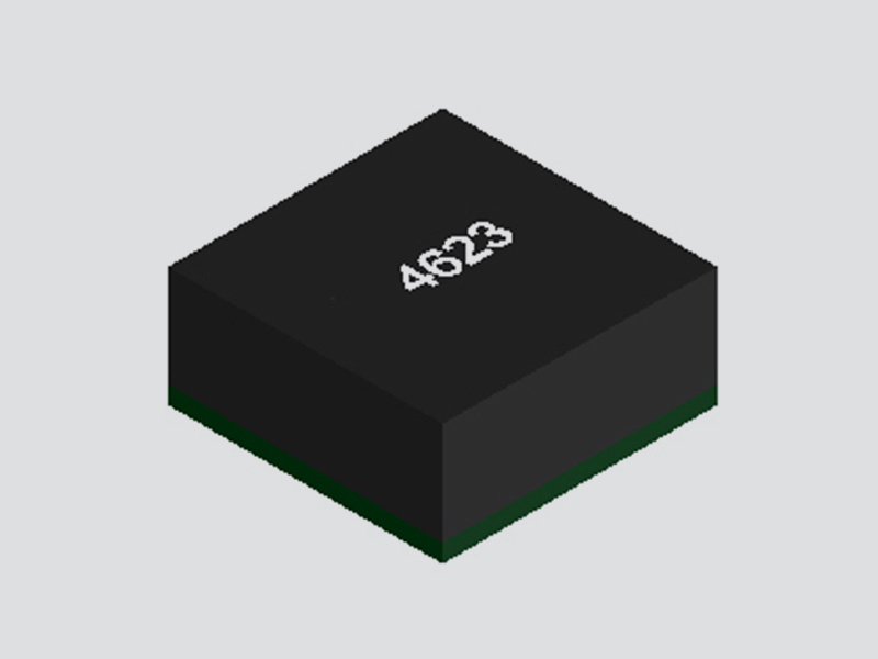
FHT4623 DC/DC Adjustable Buck Converter Power Module ( 4.2V-20V Input, 0.6V-5.5V Output )
Details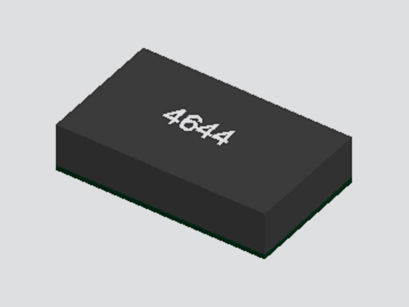
FHT4644 Ultra-Thin Multi-Channel DC/DC Buck Power Module ( 4.0V ~ 15V Input, 0.8V ~ 5.5V Output )
Details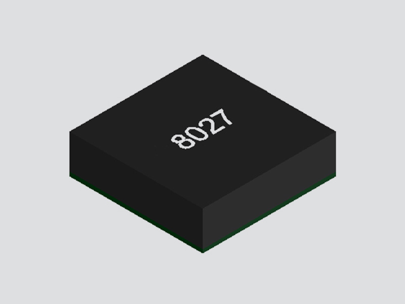
FHT8027C DC/DC Buck Converter Integrated Power Module ( 5V-60V Input, 2.5V-24V Output )
Details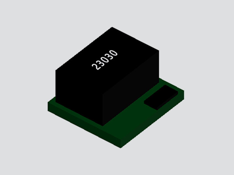
FHT23030 DC/DC Adjustable Buck Converter Module ( 4.5V–17V Input, 0.9V–6V Output )
Details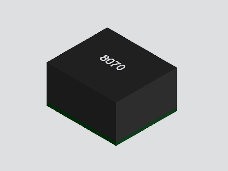
MPPM8070 DC/DC Adjustable Buck Converter Module ( Input 4.5V–18V, Output 0.6V-15V )
Details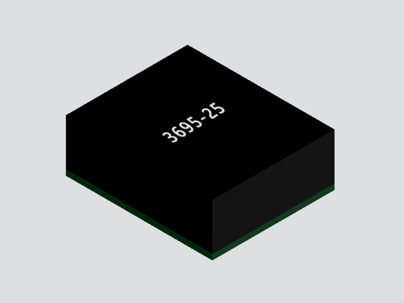
FHM3695 DC/DC Adjustable Buck Power Module ( 4V-16V Input, 0.6V-5.5V Output )
Details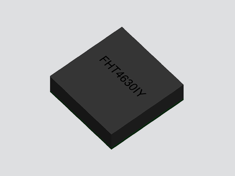
FHT4630 Dual-Channel DC/DC Adjustable Buck Converter Module ( 4.5V~15V Input, 0.6V ~ 1.8V Output )
Details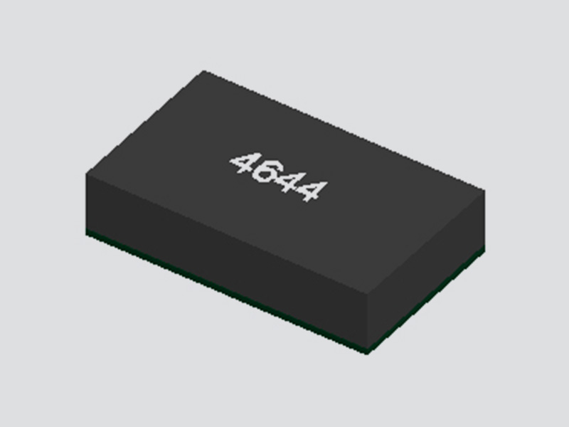
FHT4644C/D 4-Channel DC/DC Buck Power Module with Adjustable Outputs ( 4.5V-14V Input, 0.6V-5.5V Output )
Details
FHT4644F 4-Channel DC/DC Magnetically Integrated Buck Power Module (SiP) | 4.5V to 16V Input, 0.6V to 5.5V Output
Details
FHT4644H 4 Channel Integrated DC/DC Adjustable Buck Power Module ( 4.0V ~ 14V Input, 0.6V ~ 5.5V Output )
Details
FHT4644L 4-Channel Integrated Adjustable Buck DC/DC Power Module ( 4.0V ~ 15V Input, 0.8V ~ 5.5V Output )
Details
UDM2520I Integrated DC/DC Buck Step-Down Power Module ( 2.3V-5.5V Input, 0.8V-3.3V Output )
Details
UDM22010 Integrated DC-DC Buck Step-Down Power Module ( 2.3V-5.5V Input, 1.2V-3.3V Output )
Details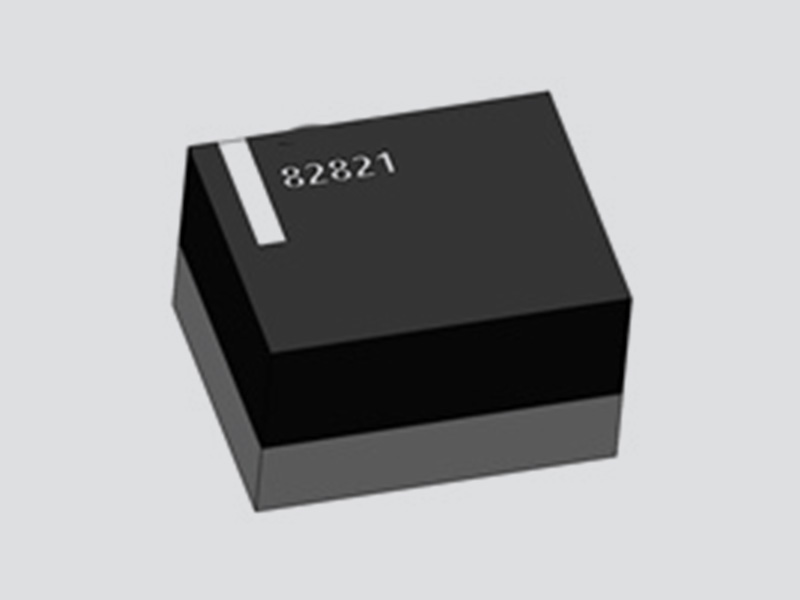
UDM82821 Integrated Magnetic DC-DC Buck Step-Down Power Module ( 2.3V-5.5V Input, 1.2V-3.3V Output )
Details
UDM82821adj Magnetically Integrated DC-DC Buck Power Module ( 2.5V-5.5V Input, 0.8V~4.0V Output )
Details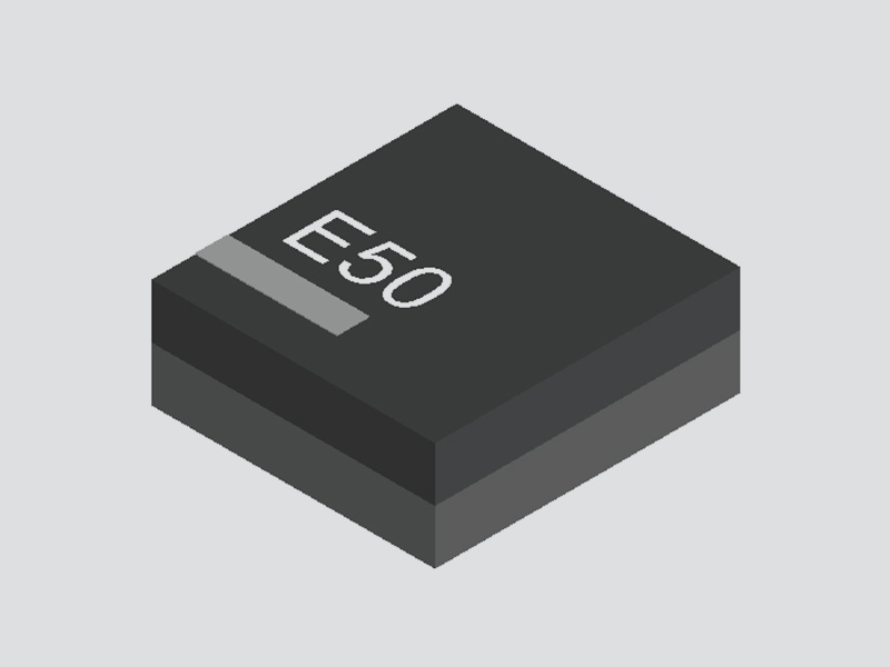
UDM81256 Integrated DC-DC Boost Power Module ( 2.5V-5.5V Input, Fixed 5V Output )
Details
UDM92403 Integrated DC-DC Boost Step-Up Power Module ( 0.7V-5.5V Input, Adjustable 1.8V-5.5V Output )
Details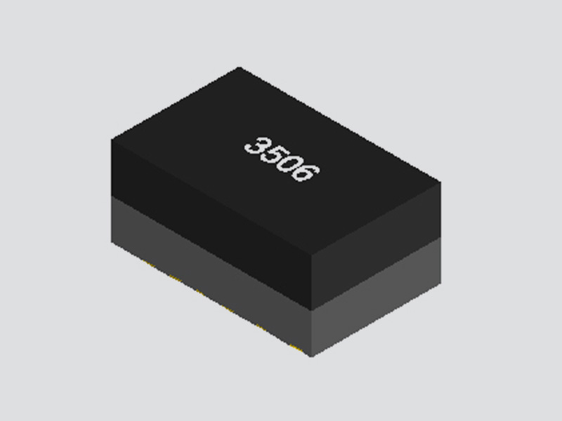
UDM3506 Integrated DC-DC Buck Step-Down Power Converter Module ( 4.7V-36V Input, 0.8V Output )
Details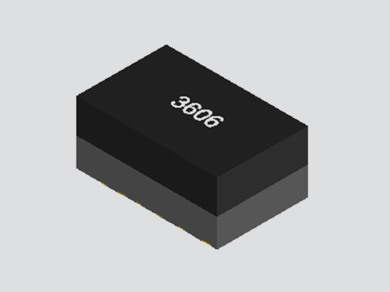
UDM3606 Integrated Medium Voltage DC-DC Buck Step-Down Power Module ( 4.5V-18V Input, 0.6V-5.5V Output )
Details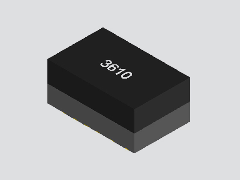
UDM3610 Integrated Medium Voltage DC-DC Buck Step-Down Power Supply Module ( 4.5V-18V Input, 0.6V-5.5V output )
DetailsFerrite Ceramic Substrate with Integrated Power Inductor and Capacitors,Low EMI Noise, Ultra-Compact
Synchronous Rectification Technology for High Efficiency
Control Mode Selection: Automatic PFM/PWM Switching or Forced PWM Mode
Light Load Operation with Low Ripple Voltage PFM Mode
Voltage Accuracy of ±2.5% Over Full Load Current Range
Wide Input Voltage Range: 2.7V to 5.5V
Maximum Load Current: 1.5A (800mA for Output Voltages of 2.5V or 3.3V)
Fixed Output Voltage: 1.0V to 3.3V (Factory Set)
Internal Soft Start and Over current Protection
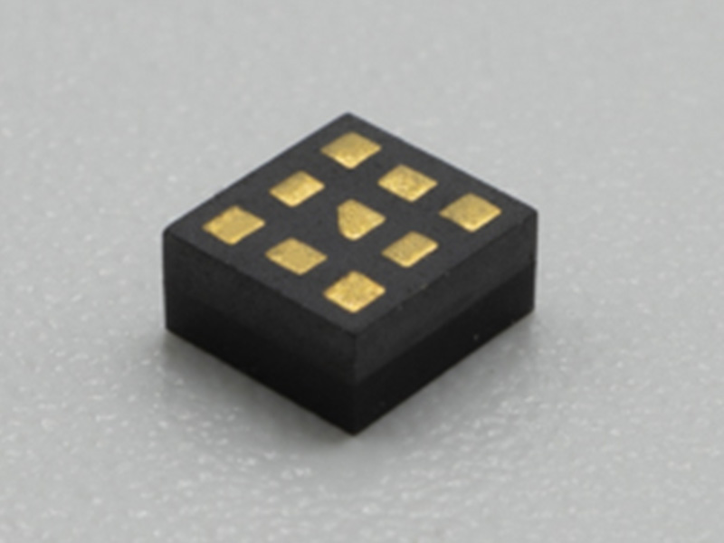
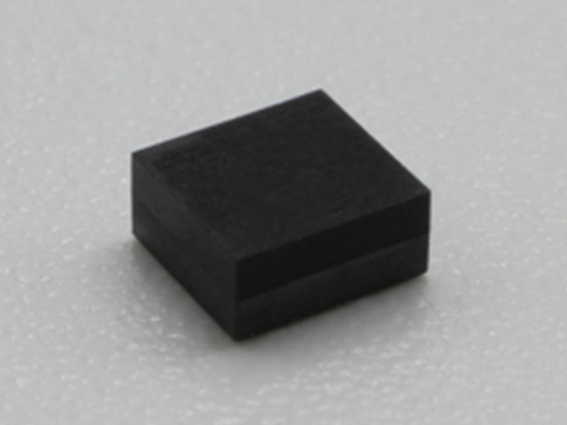
The UDM2826I series is designed for space-constrained or noise-sensitive low-power buck DC-DC converters. The device uses an inductor-embedded ferrite substrate to reduce radiated EMI noise and conducted noise. It is encapsulated in a plastic package to enhance mounting reliability.
By adding an output capacitor, it can be used as an LDO alternative. Its low noise and easy-to-use features ensure reliable power quality.
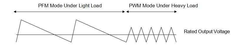
The device, when set to automatic PFM/PWM switching mode (MODE=L), operates in PFM mode at light loads to extend battery life. Under heavier loads, it automatically switches to PWM mode using synchronous rectification technology to maintain high efficiency.
When set to forced PWM mode (MODE=H), the device provides excellent output voltage accuracy over the entire load range. It maintains a voltage accuracy of ±2.5% over the current range of 0 to 1.5A.
When used as a reference voltage source, it is recommended to set the device to forced PWM mode (MODE=H). This can be achieved by directly connecting the MODE pin to VIN.
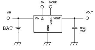
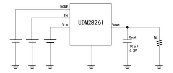
UDM2826I Typical Application Circuit
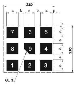
Dimensions

Symbol | Dimension(mm) | Symbol | Dimension(mm) |
W | 2.6±0.2 | c | 0.5±0.1 |
L | 2.8±0.2 | d | 0.44±0.1 |
T | 1.35 MAX | e | 0.5±0.1 |
a | 0.26±0.2 | f | 0.35±0.1 |
b | 0.49±0.1 | g | 0.4±0.1 |
Pin Functions
Pin | Symbol | I/O | Description |
1 |
MODE |
Input | Mode Selection Pin (MODE) The MODE pin must not be left floating. MODE=H: Low-noise mode, forces the device to operate in PWM mode. MODE=L: Automatic switching mode, the device operates in PFM mode at light loads and switches to PWM mode at heavy loads. |
2,3 | Vout | Output | Regulated Output Pin (Vout) Connect the output load between this pin and GND. |
4,8,9 | GND | - | Ground Pin (GND) |
5,6 | Vin | Input | The Vin pin provides current to the internal regulator of the UDM2826I. |
7 |
EN |
Input |
This is the on/off control pin for the device. Connecting the pin to GND: Keeps the device in the off mode. Pulling the pin to VIN: Enables the device with soft-start functionality. Do Not Leave Floating: The EN pin must not be left floating. If the pin is left open, the device may turn off at an output current of 100mA. Control States: EN = H: Device is enabled (on). EN = L: Device is disabled (off). |
Absolute Maximum Ratings
Parameter | Symbol | Range | Unit |
Input Voltage | Vin,EN | 6.2 | V |
Operating Ambient Temperature | Ta | -40 to +85 | ℃ |
IC Operating Temperature | TIC | -40 to +105 | ℃ |
Storage Temperature | TSTO | -40 to +85 | ℃ |
Electrical Characteristics(Ta = 25℃)
Parameter | Symbol | Conditions | Min. | Typ. | Max. | Unit |
Input Voltage | Vin | 2.7 | 3.7 | 5.5 | V | |
UVLO Voltage | UVLO | 1.0 | 1.4 | 1.8 | V | |
Input Leakage Current | Iin-off | Vin=3.7V, | 0 | 2 | μA |
| EN=0V | ||||||||
| Output Voltage Accuracy | Vout | 1 | 2.5 | % | ||||
| Output Voltage Range | Vout | Vin-Vout>0.7V | UDM2826I1V0K15A | 0.975 | 1 | 1.025 | V | |
| UDM2826I1V2K15A | 1.17 | 1.2 | 1.23 | |||||
| UDM2826I1V6K15A | 1.56 | 1.6 | 1.64 | |||||
| UDM2826I1V8K15A | 1.755 | 1.8 | 1.845 | |||||
| UDM2826I2V5K08A | 2.438 | 2.5 | 2.563 | |||||
| UDM2826I3V3K08A | 3.218 | 3.3 | 3.383 | |||||
| Load Current Range Overview | Iout | UDM2826I1V0K15A | 0 | 1500 | mA | |||
| UDM2826I1V2K15A | ||||||||
| UDM2826I1V6K15A | ||||||||
| UDM2826I1V8K15A | ||||||||
| UDM2826I2V5K08A | 0 | 800 | ||||||
| UDM2826I3V3K08A | ||||||||
| Ripple Voltage | Vrpl | Vin=3.7V, Iout=1500mA, BW=20MHz | UDM2826I1V0K15A | 15 | mV | |||
| UDM2826I1V2K15A | ||||||||
| UDM2826I1V6K15A | ||||||||
| UDM2826I1V8K15A | ||||||||
| Vin=5V,Iout=1500mA, BW=20MHz | UDM2826I2V5K08A | |||||||
| Vin=5V,Iout=800mA, BW=20MHz | UDM2826I3V3K08A | |||||||
| Efficiency | EFF | Vin=3.7V, Iout=300mA | UDM2826I1V0K15A | 85 | % | |||
| UDM2826I1V2K15A | 86 | |||||||
| UDM2826I1V6K15A | 88 | |||||||
| UDM2826I1V8K15A | 90 | |||||||
| UDM2826I2V5K08A | 93 | |||||||
| Vin=5V,Iout=300mA | UDM2826I3V3K08A | 93 | ||||||
| EN Control Voltage | VENH | ON: Enable | 1.4 | Vin | V | |||
| VENL | OFF:Disable | 0 | 0.3 | V | ||||
| Switching Frequency | Fosc | 2.5 | 3 | 3.5 | MHz | |||
| (SW Frequency) | ||||||||
| Overcurrent Protection | OCP | UDM2826I1V0K15A | 1500 | mA | ||||
| UDM2826I1V2K15A | ||||||||
| UDM2826I1V6K15A | ||||||||
UDM2826I1V8K15A | ||||||||
UDM2826I2V5K08A | 800 | |||||||
UDM2826I3V3K08A | ||||||||
Soft Start Time | Ton | 1 | ms | |||||
1 The external capacitor (Cout: 10μF) should be placed near the device to ensure proper operation.
2 The above characteristics were tested using the test circuit described in Section 8.
PFM/PWM Modes
If the load current decreases, the converter will automatically enter PFM (Pulse Frequency Modulation) mode. In PFM mode, the device operates in discontinuous current mode with sporadic switching pulses to maintain high efficiency under light load conditions.
The device uses constant on-time control in PFM operation, which produces low ripple voltage and precise output voltage compared to other PFM architectures. Due to this architecture, the DC output voltage can be maintained within ±2.5% of the nominal voltage. By increasing the output capacitance, the output ripple voltage in PFM mode can be further reduced.
The transition between PFM and PWM modes is also smooth. The current threshold for transitioning between PFM and PWM modes depends on factors such as Vin and Vout, but the approximate threshold is around (100~200) mA.
UVLO(Undervoltage Lockout)
Even if the EN pin is held high, the input voltage (Vin) must reach or exceed the UVLO voltage (2.0V typical) before the device starts up. The UVLO feature prevents uncertain operation at low Vin levels.
Soft Start
The device features an internal soft start function to limit inrush current during startup. The soft start system gradually increases the switch time from the minimum pulse width to normal operation. Due to this feature, the output voltage gradually increases from zero to the rated voltage during startup. The nominal soft start time is 0.3ms.
EN
When the EN pin is set to a high logic level, the device begins operation and starts up with a soft start. The EN pin must not be left floating; if it is open-circuit, the device may work under light load but fail to operate under heavy load.
Pulling the EN pin to a low logic level will force the device to shut down.
100% Duty Cycle Operation
The device can operate in a 100% duty cycle mode, where the high-side switch is always on, providing a lower voltage drop from input to output.
When Vin and Vout become close and the duty cycle approaches 100%, the switching pulses will skip the nominal switching cycle, and the output voltage ripple may be greater than under other conditions. However, this does not indicate a fault in the device.
Symbol | Dimension(mm) |
a | 0.65 |
b | 0.3 |
c | 0.6 |
d | 0.6 |
e | 0.3 |
f | 0.1 |
g | 0.15 |
Recommended Reflow Soldering Profile
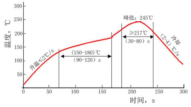
Note: For bulk and opened original packaging products, store them in a dry cabinet (the relative humidity in the dry cabinet should be kept below 10%). For unopened original packaging products, store them in a dry cabinet whenever possible.
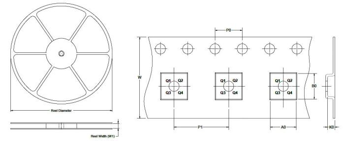
Reel and Tape Main Dimensions
Reel Diameter | Reel Width W1 (mm) | A0 (mm) | B0 (mm) | K0 (mm) | P0 (mm) | P1 (mm) | W (mm) |
Pin1 Quadrant |
MOQ |
7″ | 8.8 | 2.80 | 3.10 | 1.40 | 4.0 | 4.0 | 8.0 | Q1 | T/R,3000pcs/R |
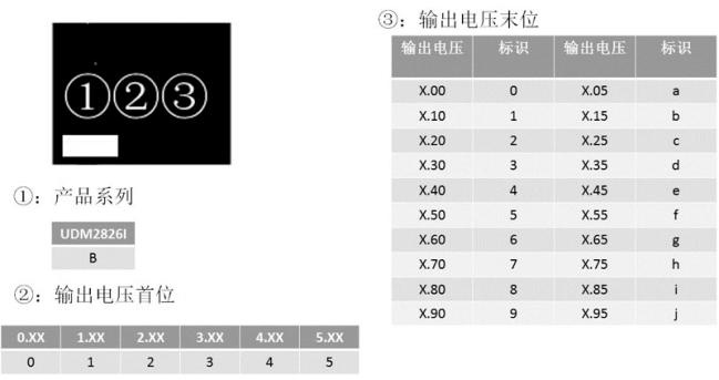
Model | Output Voltage | Device Specific Features | MOQ |
UDM2826I1V0K15A | 1.0V | Standard Types | T/R,3000pcs/R |
UDM2826I1V2K15A | 1.2V | Standard Types | T/R,3000pcs/R |
UDM2826I1V6K15A | 1.6V | Standard Types | T/R,3000pcs/R |
UDM2826I1V8K15A | 1.8V | Standard Types | T/R,3000pcs/R |
UDM2826I2V5K08A | 2.5V | Standard Types | T/R,3000pcs/R |
UDM2826I3V3K08A | 3.3V | Standard Types | T/R,3000pcs/R |
The output voltage can be set from 1.0V to 3.3V. For detailed information, please contact us .
| Item | Description | Reel/Tray | Pcs/Roll | G.W | N.W | QTY/Carton | Package Size |
| UDM2826I | 2.7V~5.5V Input, 1V-3.3V Output, Integrated DC-DC Buck Step-Down Power Module, Efficiency up to 93% |
| 3,000pcs | 0.28kgs | 0.11kgs | 3,000pcs | 150*150*50mm |
Discover all the technical specifications by downloading the datasheet today.
| Part Number |
Output Current
(A) |
Input Voltage
(V) |
Output Voltage
(V) |
Dimensions(mm) |
Maximum
Efficienc |
Factory Pack
Quantity |
Footprint 3D | Datasheet | Sample |
| UDM2520I | 0.6A | 2.3V ~ 5.5V | 0.8V~3.3V | 2.5mm × 2mm x 1.1mm | 94% | 3,000pcs |  |
 |
|
| UDM22006 | 0.6A | 2.3V~5.5V | 1.2V~3.3V | 2.5mm x 2mm x 1.1mm | 95% | 3,000pcs | |
|
|
| UDM22010 | 1A | 2.3V ~ 5.5V | 1.2V ~ 3.3V | 2.5mm x 2mm x 1.1mm | 95% | 3,000pcs | |
|
|
| UDM82821adj | 1A | 2.5V~5.5V | 0.8V~4V | 2.5mm × 2mm x 1.1mm | 95% | 3,000pcs | |
|
|
| UDM82821 | 1.2A | 2.3V~5.5V | 1.2V~3.3V | 2.5mm × 2mm x 1.1mm | 95% | 3,000pcs | |
|
|
| UDM2826I | 1.5A | 2.7V ~ 5.5V | 1V ~ 3.3V | 2.8mm × 2.6mm x 1.1mm | 93% | 3,000pcs | |
|
|
| UDM3606 | 0.6A | 4.5V-18V | 0.6V-5.5V | 5mm×3.2mm×2.2mm | 95% | 3,000pcs | |
|
|
| UDM3506 | 0.6A | 4.7V-36V | 0.8V | 5mm×3.2mm×2.2mm | 88% | 3,000pcs | |
|
|
| UDM3610 | 1.2A | 4.5V~18V | 0.6V~5.5V | 5mm×3.2mm×2.2mm | 95% | 3,000pcs | |
|
|
| UDM92403 | 0.3A | 0.7V~5.5V | 1.8V~5.5V | 2.5mm×2mm x 1.1mm | 93% | 3,000pcs | |
|
|
| UDM81256 | 1A | 2.5V ~ 5.5V | 5V | 2.8mm×2.6mm×1.35mm(1.1mm) | 95% | 3,000pcs | |
|
|
| FHT4644 | 4A | 4.0V ~ 15V | 0.8V ~ 5.5V | 9mm x 15mm x 4.32mm | 92% | 500pcs | |
|
|
| FHT4644H | 4A | 4.0V ~14V | 0.6V ~ 5.5V | 9mmx15mmx4.32mm | 92% | 500pcs | |
|
|
| FHT4644C/D | 4A | 4.5V-14V | 0.6V-5.5V | 9mmx15mmx4.32mm | 92% | 500pcs | |
|
|
| FHT4644F | 4A | 4.5V ~ 16V | 0.6V ~ 5.5V | 9.0mmx15mmx4.32mm | 92% | 500pcs | |
|
|
| FHT4644L | 4A | 4.0V ~15V | 0.8V ~ 5.5V | 9mmx15mmx1.82mm | 92% | 500pcs | |
|
|
| FHT4630 | 18A+18A | 4.5V~15V | 0.6V ~ 1.8V | 16mm × 16mm × 5.01mm | 94% | 500pcs | |
|
|
| FHT3860 | 6A | 2.3V-5.5V | 0.5V-3.3V | 4mm x 6mm x 1.6mm | 94% | 500pcs | |
|
|
| FHM3695-25 | 20A | 4V-16V | 0.6V-5.5V | 10mm × 12mm ×4.32mm | 95% | 500pcs | |
|
|
| FHT4623 | 3A | 4.2V-20V | 0.6V-5.5V | 6.75mm x 6.75mm x 2.95mm | 95% | 500pcs | |
|
|
| MPPM8070 | 2A | 4.5V-18V | 0.6V-15V | 8mm×7mm × 4.32(2.5mm) | 93% | 500pcs | |
|
|
| FHT4618 | 6A | 4.5V-24V | 0.6V-5.5V | 15mm×9mm×4.32mm | 95% | 500pcs | |
|
|
| FHT23030 | 3A | 4.5V-17V | 0.9V-6V | 3mm×2.8mm×1.4mm | 94% | 500pcs | |
|
|
| FHT3550 | 5A | 3.5V-40V | 1.0V-12.0V | 12mm x 12mm x 4.32mm | 95% | 500pcs | |
|
|
| FHT8027C | 4A | 5V-60V | 2.5V-24V | 15mm×15mm×4.32mm | 95% | 500pcs | |
|

Data Centers and Server Farms

Medical Devices

Aerospace and Defense

Automotive Electronics

Industrial and Automation

Consumer Electronics
Telecommunications and Networking
We are committed to delivering high-quality, innovative electronic components that empower industries to achieve greater efficiency.
Follow Us