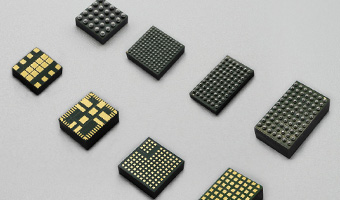


 Integrated Magnetic Power Module
Buck (Step-Down)-Low Voltage
Buck (Step-Down)-Medium Voltage
Boost (Step-Up)
DC-DC Power Modules
Integrated Magnetic Power Module
Buck (Step-Down)-Low Voltage
Buck (Step-Down)-Medium Voltage
Boost (Step-Up)
DC-DC Power Modules
 Magnetically Integrated Power Module (SiP)
Buck (Step-Down)-Multiple Outputs
Buck (Step-Down)
Boost (Step-Up)
Magnetically Integrated Power Module (SiP)
Buck (Step-Down)-Multiple Outputs
Buck (Step-Down)
Boost (Step-Up)
 Customized DC-DC Converters
Tailored Power Modules: Precision Solutions for Your Unique Needs.
Contact Us Today to Discuss Your Project!

DC-DC Power Modules
Customized DC-DC Converters Explore DC-DC Converters
UDM22006 DC DC Integrated Magnetic Power Module ( Input 2.3V–5.5V, output 1.2V-3.3V )
Details
FHT3550 DC/DC Adjustable Buck Power Module ( 3.5V-40V Input, 1.0V-12.0V Output )
Details
FHT3860 DC/DC Step-Down Buck Power Module ( 2.3V-5.5V Input, 0.5V-3.3V Output )
Details
FHT4618 Integrated DC/DC Adjustable Buck Power Module ( 4.5V-24V Input, 0.6V-5.5V Output )
Details
FHT4623 DC/DC Adjustable Buck Converter Power Module ( 4.2V-20V Input, 0.6V-5.5V Output )
Details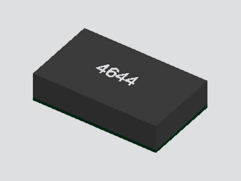
FHT4644 Ultra-Thin Multi-Channel DC/DC Buck Power Module ( 4.0V ~ 15V Input, 0.8V ~ 5.5V Output )
Details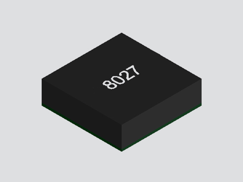
FHT8027C DC/DC Buck Converter Integrated Power Module ( 5V-60V Input, 2.5V-24V Output )
Details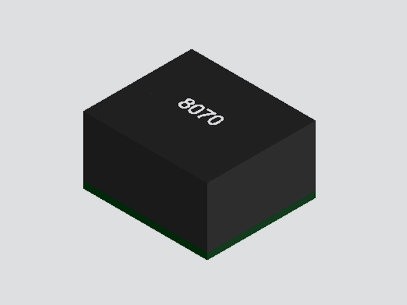
MPPM8070 DC/DC Adjustable Buck Converter Module ( Input 4.5V–18V, Output 0.6V-15V )
Details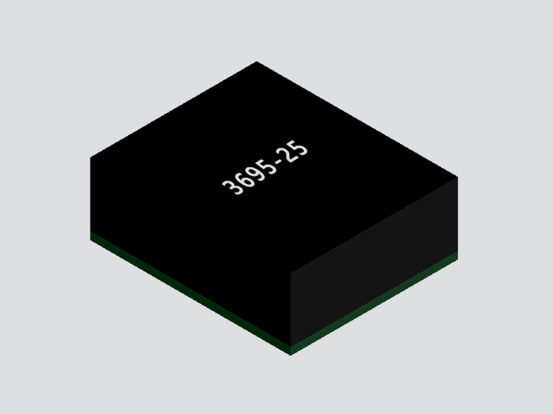
FHM3695 DC/DC Adjustable Buck Power Module ( 4V-16V Input, 0.6V-5.5V Output )
Details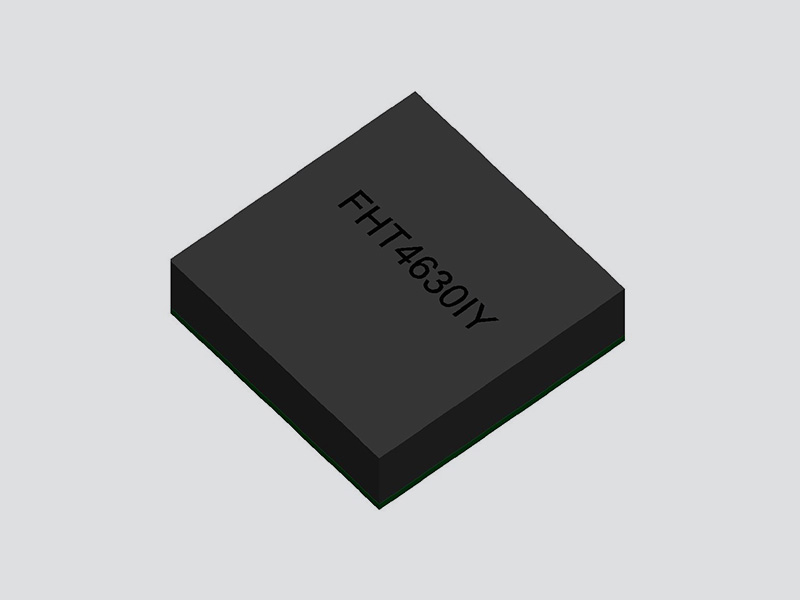
FHT4630 Dual-Channel DC/DC Adjustable Buck Converter Module ( 4.5V~15V Input, 0.6V ~ 1.8V Output )
Details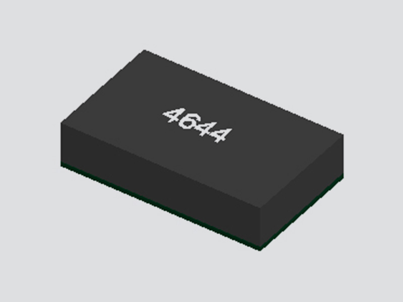
FHT4644C/D 4-Channel DC/DC Buck Power Module with Adjustable Outputs ( 4.5V-14V Input, 0.6V-5.5V Output )
Details
FHT4644F 4-Channel DC/DC Magnetically Integrated Buck Power Module (SiP) | 4.5V to 16V Input, 0.6V to 5.5V Output
Details
FHT4644H 4 Channel Integrated DC/DC Adjustable Buck Power Module ( 4.0V ~ 14V Input, 0.6V ~ 5.5V Output )
Details
FHT4644L 4-Channel Integrated Adjustable Buck DC/DC Power Module ( 4.0V ~ 15V Input, 0.8V ~ 5.5V Output )
Details
UDM2520I Integrated DC/DC Buck Step-Down Power Module ( 2.3V-5.5V Input, 0.8V-3.3V Output )
Details
UDM2826I Integrated DC-DC Buck Step-Down Power Module ( 2.7V-5.5V Input, 1.0V-3.3V Output )
Details
UDM22010 Integrated DC-DC Buck Step-Down Power Module ( 2.3V-5.5V Input, 1.2V-3.3V Output )
Details
UDM82821 Integrated Magnetic DC-DC Buck Step-Down Power Module ( 2.3V-5.5V Input, 1.2V-3.3V Output )
Details
UDM82821adj Magnetically Integrated DC-DC Buck Power Module ( 2.5V-5.5V Input, 0.8V~4.0V Output )
Details
UDM81256 Integrated DC-DC Boost Power Module ( 2.5V-5.5V Input, Fixed 5V Output )
Details
UDM92403 Integrated DC-DC Boost Step-Up Power Module ( 0.7V-5.5V Input, Adjustable 1.8V-5.5V Output )
Details
UDM3506 Integrated DC-DC Buck Step-Down Power Converter Module ( 4.7V-36V Input, 0.8V Output )
Details
UDM3606 Integrated Medium Voltage DC-DC Buck Step-Down Power Module ( 4.5V-18V Input, 0.6V-5.5V Output )
Details
UDM3610 Integrated Medium Voltage DC-DC Buck Step-Down Power Supply Module ( 4.5V-18V Input, 0.6V-5.5V output )
Details3A continuous output current
Input voltage range: 4.5V-17V
Output voltage: 0.9V-6V
CoT control topology
40uA quiescent operating current
Power-saving mode for light-load efficiency
Power good (PG) output indication
Programmable soft-start
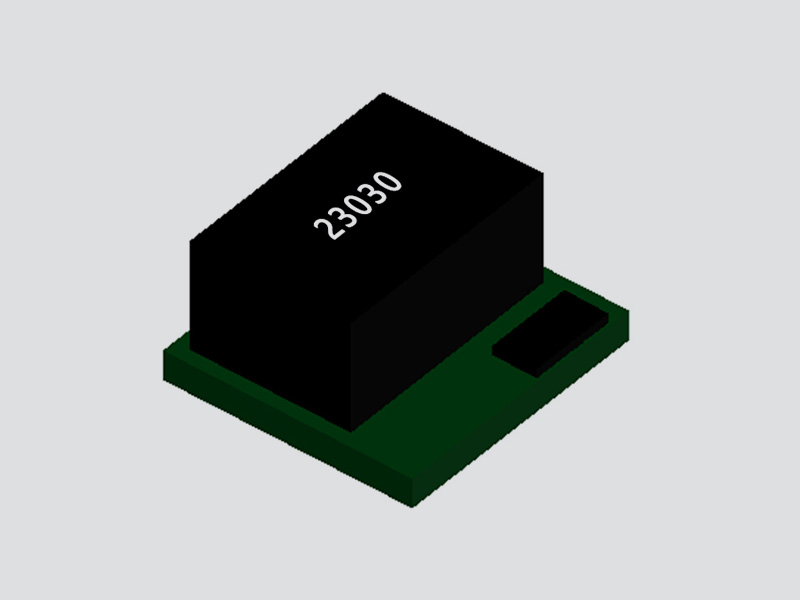
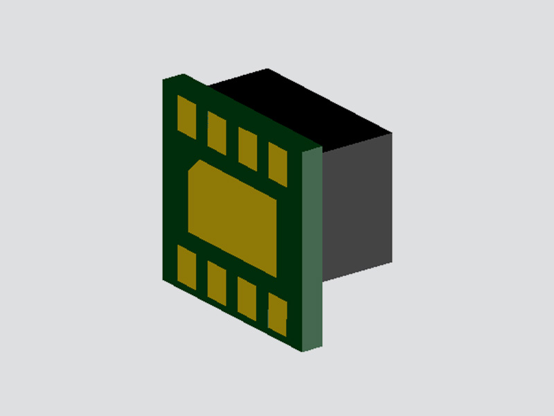
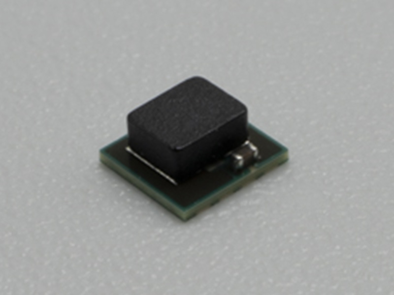
Small-size LGA package: (3mm×2.8mm×1.4mm)
Industrial Equipment
Telecommunications and Networking Systems
Solid State Drives
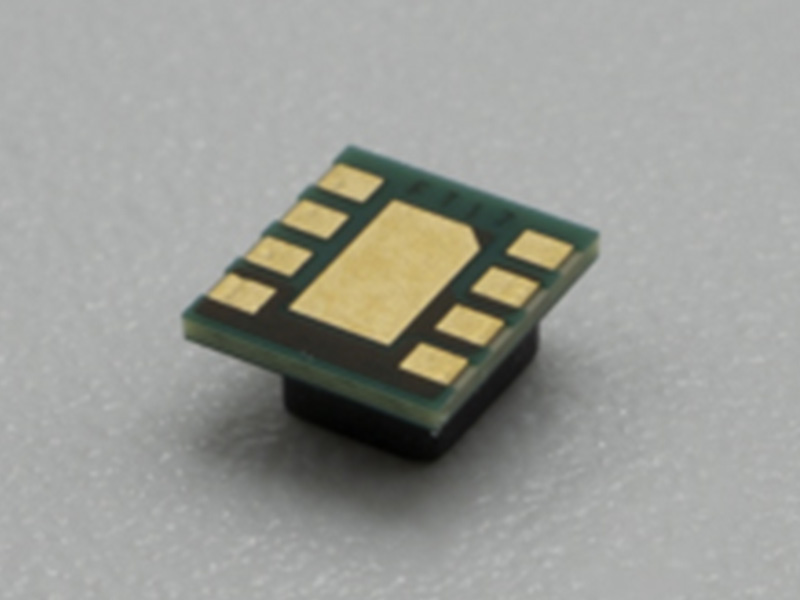
The FHT23030 is a non-isolated DC/DC power module that provides a complete power solution.
It simplifies design by requiring only a minimal number of resistor and capacitor components for its periphery. With an input voltage range of 4.5~17V and a rated output current of 3A, the output voltage is adjustable, and it
exhibits excellent load regulation and line regulation. To maximize efficiency, the FHT23030 operates in PFM mode with a nominal switching frequency of 2MHz and
automatically enters power-saving mode during light loads.
In power-saving mode, the typical quiescent operating current of the module is 40μA. The FHT23030 features comprehensive protection characteristics, including over-current protection (OCP), short-circuit protection (SCP), under-voltage lockout protection (UVLO), and over-temperature protection.


| Pin | Symbol | Description |
| 1 | EN | Enable Pin:Connecting EN to high level turns on the module,while connecting EN to low level turns off the module.When the module is off,this pin has an internal 400KQ pull-down resistor |
| 2 | VIN | Voltage Input Pin:Connect VIN to the input power supply to power the module. |
| 3 | GND | Module Ground. |
| 45 | VOUT | Output Voltage Pin |
| 6 | FB | Voltage Feedback Pin:This pin connects to an external voltage divider to adjust the output voltage. |
| 7 | PG | Power Good Output Indicator Pin:This pin should be connected to a pull-up resistor to any voltage lower than 6V.If not used,leave t floating. |
| 8 | SS | Soft-Start Pin:Connect an external capacitor to ground on this pin to set the rise time of the internal reference voltage. |
| Thermal Pad | Exposed Heat Sink Pad:Must be connected to GND.Soldering is required to improve thermal dissipation and mechanical reliability. |
Input current
Absolute Maximum Ratings | Condition | Minimum | Nominal value | Maximum | Unit |
VIN, | -0.3 | 20 | V | ||
EN ,SS | -0.3 | 7 | V | ||
PG ,FB | -0.3 | 7 | V | ||
VOUT | -0.3 | 7 | V | ||
PG Sink Current | 10 | mA | |||
Storage temperature | -55 | +125 | ℃ | ||
Input characteristic | Condition | Minimum | Nominal value | Maximum | Unit |
Input Voltage range | 4.5 | 17 | V |
Input Current
Input current at full load | VIN =12V ,VOUT =1V ,IOUT=3A | 0.36 | A | ||
Input current at low voltage and full load | VIN =5V ,VOUT =1V ,IOUT=3A | 0.75 | A | ||
Input current at no load | VIN =12V ,VOUT =1V ,IOUT=0A | 0.75 | mA | ||
Input current when switched off | VIN =12V ,VEN=0V | 1.5 | μA | ||
General requirements | Condition | Minimum | Nominal value | Maximum | Unit |
PWM Switching Frequency | VOUT = 1.8V ,IOUT = 1A | 2 | MHz | ||
PG Pull-up Resistor Voltage | 6 | V | |||
Efficiency | VIN =8V ,VOUT =3.25V ,IOUT=1.5A | 92% | % | ||
Functionality | Condition | Minimum | Nominal value | Maximum | Unit |
EN High-Level Input Voltage | 0.9 | 0.73 | V | ||
EN Low-Level Input Voltage | 0.63 | 0.33 | V | ||
PGOOD Threshold Indicator Value | VOUT rise | 92 | 95 | 99 | % |
VOUT drop | 87 | 90 | 94 | % | |
Output characteristic | Condition | Minimum | Nominal value | Maximum | Unit |
Output Voltage | Adjusted by the RFB resistor. | 0.9 | 6 | V | |
Line Regulation | VOUT= 1V ,4.5V < VIN< 17V , ILOAD = 3A | ±1 | % | ||
Load Regulation | VIN=12V ,VOUT=1V,0A < ILOAD ≤ 3A | ±1 | % |
| Protection Characteristics | Condition |
Minimum |
Nominal value |
Maximum |
Unit |
Undervoltage Lockout (UVLO) Threshold | VIN drop | 3.8 | |||
VIN rise | 4.2 | 4.5 | |||
Thermal Shutdown Threshold | Junction temperature rise | 160 | ℃ | ||
Junction temperature drop | 140 | ℃ | |||
Structural Characteristics | Condition | Minimum | Nominal value | Maximum | Unit |
Size | Length | 2.95 | 3 | 3.05 | mm |
Width | 2.75 | 2.8 | 2.85 | mm | |
Height | 1.4 | 1.42 | mm | ||
Environmental adaptability | Condition | Minimum | Nominal value | Maximum | Unit |
Working temperature (ambient temperature) | -40 | 110 | ℃ | ||
High temperature storage (ambient temperature) | +125℃ , 48h | 125 | ℃ | ||
High temperature operation (ambient temperature) | +85℃ , 24h; Input low-voltage, standard-voltage, and high-voltage for 8 hours each; | 85 | ℃ | ||
Low temperature storage (ambient temperature) | -55℃ , 24h | -55 | ℃ | ||
Low temperature operation (ambient temperature) | -40℃ , 24h; Input low-voltage, standard-voltage, and high-voltage for 8 hours each | -40 | ℃ | ||
Hot and humid |
High temperature and high humidity stage: 60 ℃, 95%; Low temperature and high humidity stage: 30 ℃, 95%; Cycle 10 times, each cycle lasting 24 hours |
30 |
60 | ℃ | |
Thermal shock |
At a high temperature of 125°C and a low temperature of -55°C, one hour at each temperature constitutes one cycle, with a total of 32 cycles being tested. | -55 | 125 | ℃ |
Note 1: Stresses above those listed in the "Absolute Maximum Ratings" section may cause permanent damage to the device. Prolonged exposure to any of the Absolute Maximum Ratings conditions may affect device reliability and useful life.
Note 2: The maximum continuous output current may be derated due to the junction temperature of the FHT23030.
Note 3: The performance specifications of the FHT23030 are guaranteed over an internal operating temperature range of -40°C to 125°C. Please note that the maximum internal temperature is determined by specific operating conditions in conjunction
with circuit board layout, the rated thermal resistance of the package, and other environmental factors.
The test conditions are VIN = 12V ,VOUT = 1.0V,with external capacitors CIN=2x10μF and COUT = 2x47μF, and a temperature of TA = 25。C ,unless otherwise noted.

The test conditions are VIN = 12V ,VOUT = 1.0V,with external capacitors CIN=2x10μF ,COUT = 2x47μF ,and a temperature of TA = 25。C,unless otherwise noted.

The test conditions are VIN = 12V ,VOUT = 1.0V,with external capacitors CIN=2x10μF and COUT = 2x47μF,and a temperature of TA = 25。C ,unless otherwise noted.

The test conditions are VIN = 12V ,VOUT = 1.0V,with external capacitors CIN=2x10μF ,COUT = 2x47μF ,and a temperature of TA = 25。C,unless otherwise noted.

The test conditions are VIN = 12V ,VOUT = 1.0V,with external capacitors CIN=2x10μF ,COUT = 2x47μF ,and a temperature of TA = 25。C,unless otherwise noted
The c are VIN = 12V ,VOUT = 1.0V,with external capacitors CIN=2x10μF ,COUT = 2x47μF ,and a temperature of TA = 25。C,unless otherwise noted.

The FHT23030 is a synchronous buck DC-DC voltage converter with a switching frequency of 2MHz. It can achieve a continuous output current of 3A within an input voltage range of 4.5V to 17V.
Enable Control (EN)
The FHT23030 can be enabled or disabled by setting the EN pin. When the EN pin is connected to a high level, the module is enabled. When the EN pin is connected to a low level or left floating, the module is disabled. In this mode, the typical input current is 1.5μA. The EN pin can also be used to set the undervoltage lockout (UVLO) threshold of the FHT23030, with the application circuit shown in Figure 1:

Figure 1: Undervoltage Lockout (UVLO) Voltage Divider Circuit
Soft Start (SS)
The soft-start function controls the rise slope of the output voltage within 1ms during startup, which can suppress inrush current. The FHT23030 is capable of starting up with a pre-biased output capacitor. During pre-biased startup, the two power MOSFETs cannot turn on until the internal voltage clamp sets the output voltage higher than the pre-bias voltage. When the FHT23030 is in the off state, undervoltage lockout (UVLO), or thermal shutdown state, the capacitor connected to the SS pin is discharged by an internal resistor. Returning from these states initiates a new soft-start cycle.
The startup slope of the output voltage can be set by the capacitor connected between the SS pin and GND. A constant current of 2.5μA charges the external capacitor. The given soft-start time (TSS) is set by the CSS capacitor, and the calculation formula is shown in Equation (1):
 (1)
(1)
Input Undervoltage Lockout (UVLO) Protection
When the input voltage is below 4.2V, the FHT23030 will undergo undervoltage lockout and remain in shutdown mode. If enabled under UVLO conditions, the module will remain in shutdown mode until the input voltage rises above the set threshold. When the input falls below 3.8V, the module will shut down with a hysteresis of 400mV.
Over-Temperature Protection (OTP)
When the junction temperature of the FHT23030 exceeds the threshold of 160°C, the thermal shutdown protection is activated. This protection is non-latching. Once the junction temperature drops to approximately 140°C, the module resumes operation through a soft-start sequence.
Over-Current Protection (OCP)
The FHT23030 features over-current protection to prevent damage under over-current conditions. The over-current protection function is triggered when the valley current reaches 3.6A. When the output drops to approximately 60%, the output is disabled. After a 10ms disable period, the module will restart and initiate a new soft-start cycle.
Power Good Output Indicator (PGOOD)
The PGOOD pin is an open-drain output. When the FB voltage is less than 92% of the nominal internal reference voltage, the PG pin is driven low. When the FB voltage is greater than 96% of the nominal internal reference voltage, the PG pin becomes high-impedance.
Table 1: Power Good Pin Logic Table
Module Status | PG Logic Status | ||
High Impedance | Low Level | ||
Enable (EN = High Level) | VFB ≥ VTH_PG | √ | |
VFB ≤ VTH_PG | √ | ||
Disable (EN = Low Level) | √ | ||
UVLO | 0.7V < VIN < VUVLO | √ | |
Thermal Shutdown | TJ > TSD | √ | |
Power Removal | VIN < 0.7V | √ |
Output Voltage Setting
The output voltage of the FHT23030 is set by an external feedback resistor divider, with the formula shown in Equation (2). The voltage regulation circuit is illustrated in Figure 2.

Figure 2: Voltage Divider Resistors for Setting the Output Voltage


Notes:
1. Please do not place the module on the bottom side of the board during reflow soldering to avoid it falling off.

2. For bulk and unpackaged products, store them in a desiccator(with a relative humidity of less than 10% inside). For products still in their original packaging, try to store them in a desiccator as well.
3.Before mounting the module on the board, strictly follow the baking conditions to dry the samples: bake at 125°C for more than 48 hours and control the reflow soldering temperature within 245°C.
| Product Model | Input | Output | Size &Encapsulation | Package | |
| Input Range | Nominal Input | ||||
| FHT23030 | 4.5V~17V | -- | 0.9V~6V/3A | 3mm×2.8mm×1.4mm(LGA) | Tray |
| Item | Description | Reel/Tray | Pcs/Roll | G.W | N.W | QTY/Carton | Package Size |
FHT23030 | Input 4.5V-17V, output 0.9V-6V DC/DC Integrated molded adjustable buck converter Power Module, Efficiency up to 94% |
| 500pcs | 0.45kgs | 0.01kgs | 500pcs | 210*210*50mm |
Discover all the technical specifications by downloading the datasheet today.
| Part Number |
Output Current
(A) |
Input Voltage
(V) |
Output Voltage
(V) |
Dimensions(mm) |
Maximum
Efficienc |
Factory Pack
Quantity |
Footprint 3D | Datasheet | Sample |
| UDM2520I | 0.6A | 2.3V ~ 5.5V | 0.8V~3.3V | 2.5mm × 2mm x 1.1mm | 94% | 3,000pcs |  |
 |
|
| UDM22006 | 0.6A | 2.3V~5.5V | 1.2V~3.3V | 2.5mm x 2mm x 1.1mm | 95% | 3,000pcs | |
|
|
| UDM22010 | 1A | 2.3V ~ 5.5V | 1.2V ~ 3.3V | 2.5mm x 2mm x 1.1mm | 95% | 3,000pcs | |
|
|
| UDM82821adj | 1A | 2.5V~5.5V | 0.8V~4V | 2.5mm × 2mm x 1.1mm | 95% | 3,000pcs | |
|
|
| UDM82821 | 1.2A | 2.3V~5.5V | 1.2V~3.3V | 2.5mm × 2mm x 1.1mm | 95% | 3,000pcs | |
|
|
| UDM2826I | 1.5A | 2.7V ~ 5.5V | 1V ~ 3.3V | 2.8mm × 2.6mm x 1.1mm | 93% | 3,000pcs | |
|
|
| UDM3606 | 0.6A | 4.5V-18V | 0.6V-5.5V | 5mm×3.2mm×2.2mm | 95% | 3,000pcs | |
|
|
| UDM3506 | 0.6A | 4.7V-36V | 0.8V | 5mm×3.2mm×2.2mm | 88% | 3,000pcs | |
|
|
| UDM3610 | 1.2A | 4.5V~18V | 0.6V~5.5V | 5mm×3.2mm×2.2mm | 95% | 3,000pcs | |
|
|
| UDM92403 | 0.3A | 0.7V~5.5V | 1.8V~5.5V | 2.5mm×2mm x 1.1mm | 93% | 3,000pcs | |
|
|
| UDM81256 | 1A | 2.5V ~ 5.5V | 5V | 2.8mm×2.6mm×1.35mm(1.1mm) | 95% | 3,000pcs | |
|
|
| FHT4644 | 4A | 4.0V ~ 15V | 0.8V ~ 5.5V | 9mm x 15mm x 4.32mm | 92% | 500pcs | |
|
|
| FHT4644H | 4A | 4.0V ~14V | 0.6V ~ 5.5V | 9mmx15mmx4.32mm | 92% | 500pcs | |
|
|
| FHT4644C/D | 4A | 4.5V-14V | 0.6V-5.5V | 9mmx15mmx4.32mm | 92% | 500pcs | |
|
|
| FHT4644F | 4A | 4.5V ~ 16V | 0.6V ~ 5.5V | 9.0mmx15mmx4.32mm | 92% | 500pcs | |
|
|
| FHT4644L | 4A | 4.0V ~15V | 0.8V ~ 5.5V | 9mmx15mmx1.82mm | 92% | 500pcs | |
|
|
| FHT4630 | 18A+18A | 4.5V~15V | 0.6V ~ 1.8V | 16mm × 16mm × 5.01mm | 94% | 500pcs | |
|
|
| FHT3860 | 6A | 2.3V-5.5V | 0.5V-3.3V | 4mm x 6mm x 1.6mm | 94% | 500pcs | |
|
|
| FHM3695-25 | 20A | 4V-16V | 0.6V-5.5V | 10mm × 12mm ×4.32mm | 95% | 500pcs | |
|
|
| FHT4623 | 3A | 4.2V-20V | 0.6V-5.5V | 6.75mm x 6.75mm x 2.95mm | 95% | 500pcs | |
|
|
| MPPM8070 | 2A | 4.5V-18V | 0.6V-15V | 8mm×7mm × 4.32(2.5mm) | 93% | 500pcs | |
|
|
| FHT4618 | 6A | 4.5V-24V | 0.6V-5.5V | 15mm×9mm×4.32mm | 95% | 500pcs | |
|
|
| FHT23030 | 3A | 4.5V-17V | 0.9V-6V | 3mm×2.8mm×1.4mm | 94% | 500pcs | |
|
|
| FHT3550 | 5A | 3.5V-40V | 1.0V-12.0V | 12mm x 12mm x 4.32mm | 95% | 500pcs | |
|
|
| FHT8027C | 4A | 5V-60V | 2.5V-24V | 15mm×15mm×4.32mm | 95% | 500pcs | |
|

Data Centers and Server Farms

Medical Devices

Aerospace and Defense

Automotive Electronics

Industrial and Automation

Consumer Electronics

Telecommunications and Networking