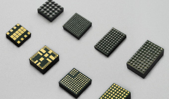


 Integrated Magnetic Power Module
Buck (Step-Down)-Low Voltage
Buck (Step-Down)-Medium Voltage
Boost (Step-Up)
DC-DC Power Modules
Integrated Magnetic Power Module
Buck (Step-Down)-Low Voltage
Buck (Step-Down)-Medium Voltage
Boost (Step-Up)
DC-DC Power Modules
 Magnetically Integrated Power Module (SiP)
Buck (Step-Down)-Multiple Outputs
Buck (Step-Down)
Boost (Step-Up)
Magnetically Integrated Power Module (SiP)
Buck (Step-Down)-Multiple Outputs
Buck (Step-Down)
Boost (Step-Up)
 Customized DC-DC Converters
Tailored Power Modules: Precision Solutions for Your Unique Needs.
Contact Us Today to Discuss Your Project!

DC-DC Power Modules
Customized DC-DC Converters Explore DC-DC Converters
UDM22006 DC DC Integrated Magnetic Power Module ( Input 2.3V–5.5V, output 1.2V-3.3V )
Details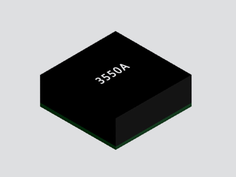
FHT3550 DC/DC Adjustable Buck Power Module ( 3.5V-40V Input, 1.0V-12.0V Output )
Details
FHT3860 DC/DC Step-Down Buck Power Module ( 2.3V-5.5V Input, 0.5V-3.3V Output )
Details
FHT4618 Integrated DC/DC Adjustable Buck Power Module ( 4.5V-24V Input, 0.6V-5.5V Output )
Details
FHT4623 DC/DC Adjustable Buck Converter Power Module ( 4.2V-20V Input, 0.6V-5.5V Output )
Details
FHT4644 Ultra-Thin Multi-Channel DC/DC Buck Power Module ( 4.0V ~ 15V Input, 0.8V ~ 5.5V Output )
Details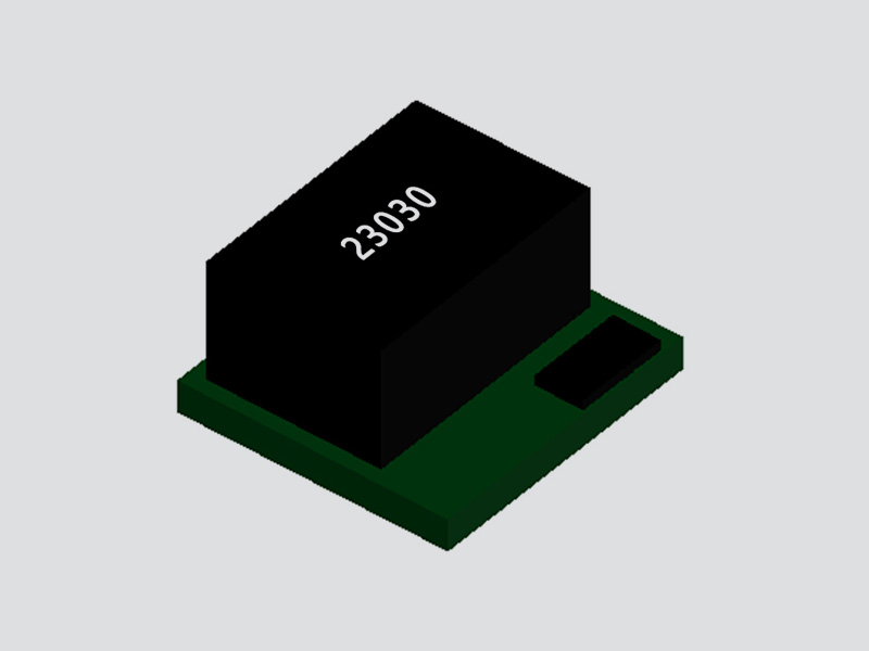
FHT23030 DC/DC Adjustable Buck Converter Module ( 4.5V–17V Input, 0.9V–6V Output )
Details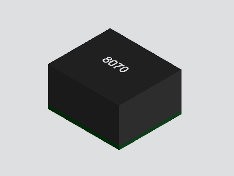
MPPM8070 DC/DC Adjustable Buck Converter Module ( Input 4.5V–18V, Output 0.6V-15V )
Details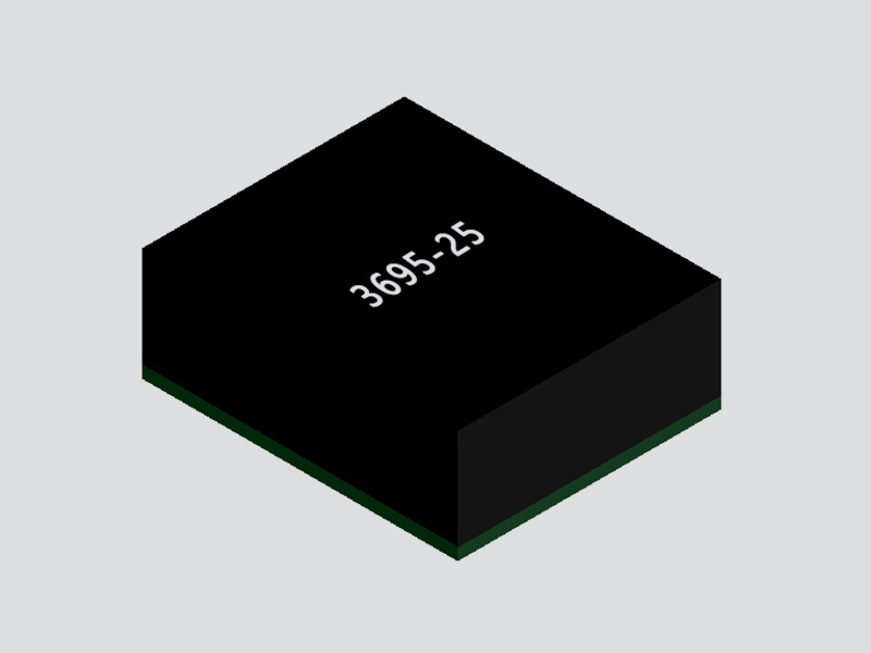
FHM3695 DC/DC Adjustable Buck Power Module ( 4V-16V Input, 0.6V-5.5V Output )
Details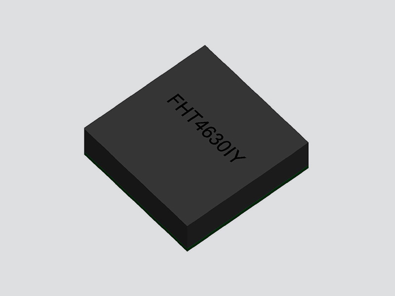
FHT4630 Dual-Channel DC/DC Adjustable Buck Converter Module ( 4.5V~15V Input, 0.6V ~ 1.8V Output )
Details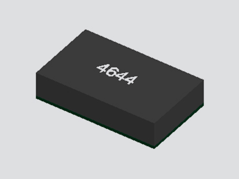
FHT4644C/D 4-Channel DC/DC Buck Power Module with Adjustable Outputs ( 4.5V-14V Input, 0.6V-5.5V Output )
Details
FHT4644F 4-Channel DC/DC Magnetically Integrated Buck Power Module (SiP) | 4.5V to 16V Input, 0.6V to 5.5V Output
Details
FHT4644H 4 Channel Integrated DC/DC Adjustable Buck Power Module ( 4.0V ~ 14V Input, 0.6V ~ 5.5V Output )
Details
FHT4644L 4-Channel Integrated Adjustable Buck DC/DC Power Module ( 4.0V ~ 15V Input, 0.8V ~ 5.5V Output )
Details
UDM2520I Integrated DC/DC Buck Step-Down Power Module ( 2.3V-5.5V Input, 0.8V-3.3V Output )
Details
UDM2826I Integrated DC-DC Buck Step-Down Power Module ( 2.7V-5.5V Input, 1.0V-3.3V Output )
Details
UDM22010 Integrated DC-DC Buck Step-Down Power Module ( 2.3V-5.5V Input, 1.2V-3.3V Output )
Details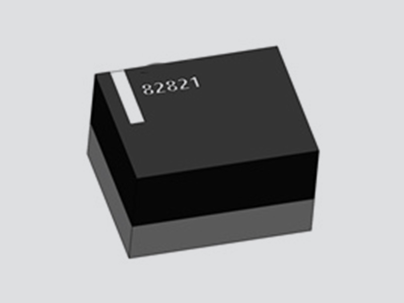
UDM82821 Integrated Magnetic DC-DC Buck Step-Down Power Module ( 2.3V-5.5V Input, 1.2V-3.3V Output )
Details
UDM82821adj Magnetically Integrated DC-DC Buck Power Module ( 2.5V-5.5V Input, 0.8V~4.0V Output )
Details
UDM81256 Integrated DC-DC Boost Power Module ( 2.5V-5.5V Input, Fixed 5V Output )
Details
UDM92403 Integrated DC-DC Boost Step-Up Power Module ( 0.7V-5.5V Input, Adjustable 1.8V-5.5V Output )
Details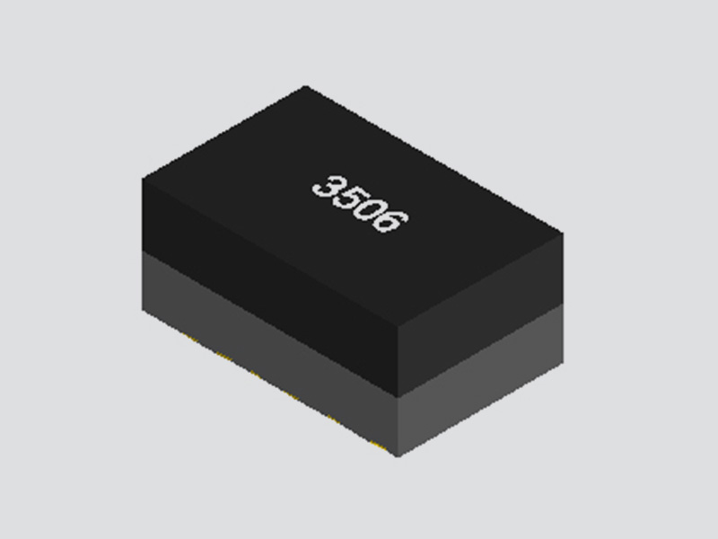
UDM3506 Integrated DC-DC Buck Step-Down Power Converter Module ( 4.7V-36V Input, 0.8V Output )
Details
UDM3606 Integrated Medium Voltage DC-DC Buck Step-Down Power Module ( 4.5V-18V Input, 0.6V-5.5V Output )
Details
UDM3610 Integrated Medium Voltage DC-DC Buck Step-Down Power Supply Module ( 4.5V-18V Input, 0.6V-5.5V output )
Details4A Full-Load Output Current
Wide Input Voltage Range: 5V-60V
Output Voltage: 2.5V-24V
Selectable Switching Frequency
Efficiency Up to 95%
15μA Shutdown Current
Programmable Soft-Start
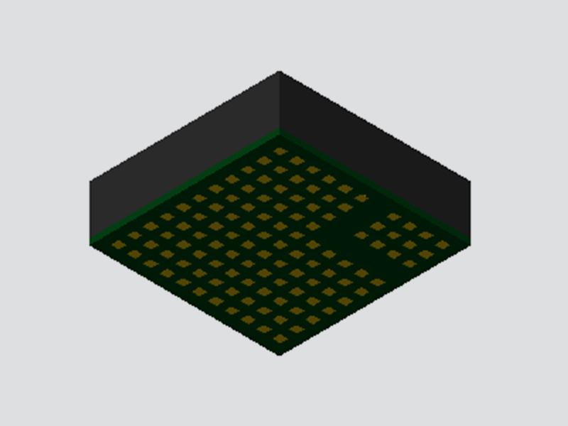
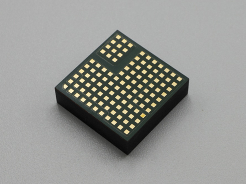
Compact LGA Package with Low Profile (15mm x 15mm x 4.32mm)
12V and 42V Automotive and Heavy-Duty Equipment
48V Telecommunications Power Supplies
Avionics and Industrial Control Systems
Distributed Power Converters
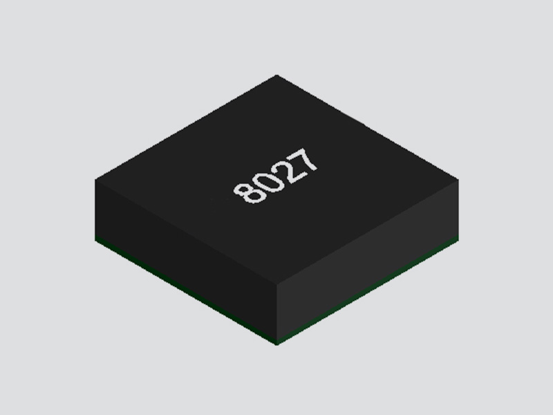
The FHT8027C is a step-down integrated molded power supply that encapsulates a switching controller, inductor, and related support components within its package. It measures 15.0×15.0×4.32 mm in size.Based on synchronous rectification Buck topology design, it can deliver a maximum output current of 4A. The power conversion efficiency can reach up to 95%.It allows for voltage conversion from 5V to 60V to 2.5V to 24V. Customers can set the switching frequency according to their needs via an external resistor, with a settable frequency range of 100kHz to 1MHz. The soft-start time can be adjusted by a small capacitor. With its integrated small-sized LGA package, only a voltage-regulating resistor, a small number of input and output filter capacitors are required for the peripheral configuration, enabling rapid completion of the power supply system setup.


| Pin | Symbol | Description |
| BANK1 | VouT | Module Voltage Output Pin. |
| BANK2 | GND | Ground Pin. |
| BANK3 | VIN | Module Voltage Input Pin. |
| A2 | ADJ | Voltage Adjustment Pin:Connect a voltage-regulating resistor with an accuracy of over 1% to GND. |
| A3、A6 | NC | Not Connected. |
| A7 | AUX | Internally connected to VouT,but do not connect it to the Load. |
| A4 | RUN | Control Pin:Grounding this pin can shut down the module.When the voltage at this pin is below 0.4V,the module is in shutdown mode.When the voltage is between 0.4V and 1.2V,the module enters standby mode.When the voltage exceeds 1.2V,the module enters operating mode.Once the voltage rises above 1.2V,an internal 10uA current source is activated,flowing through an external UVLO (Under Voltage Lock Out)resistor divider to create hysteresis.The hysteresis of the RUN pin can be adjusted via external voltage-dividing resistors. |
| B1 | RT | A resistor is connected between this pin and ground to set the switching frequency.Even when using the external SYNC pin to synchronize with an external clock,an RT resistor is still required to be connected |
| C1 | SYNC | External Clock Input for Synchronizing the Intermal Oscillator |
| A5 | SS | Used to set an external soft-start.The minimum capacitance from SS to AGND is 2.2nF. |
Absolute Maximum Ratings | Condition | Minimum | Nominal Value | Maximum | Unit |
VIN ,RUN | 80 | V | |||
SYNC | 14 | V | |||
ADJ, RT, SS pin voltages | 6 | V | |||
Storage Temperature | -55 | +125 | ℃ | ||
Input Characteristics | Condition | Minimum | Nominal Value | Maximum | Unit |
Input Voltage Range | 5 | 60 | V |
Input Current at Full Load | VIN =36V ,VOUT =12V ,IOUT=4A | 1.44 | A | ||
Input Current at Low Voltage and Full Load | VIN =16V ,VOUT =12V ,IOUT=4A | 3.15 | A | ||
Input Current at No Load | VIN =36V ,VOUT =12V ,IOUT=0A | 1 | mA | ||
Input Current in Shutdown Mode | ON/OFF=OFF ,VRUN=0V | 15 | μA | ||
General Requirements | Condition | Minimum | Nominal Value | Maximum | Unit |
Switching Frequency | Adjusted by RT Resistor | 100 | 1000 | KHz | |
Efficiency | 95 | % | |||
Functionality | Condition | Minimum | Nominal Value | Maximum | Unit |
RUN Standby to Start Threshold | 1.164 | 1.2 | 1.236 | V | |
SYNC External Clock Frequency Range | Percentage of Nominal Frequency Set by RT |
-50 |
50 |
% | |
Output Characteristics | Condition | Minimum | Nominal Value | Maximum | Unit |
Output Voltage | Adjusted by the RADJ resistor | 2.5 | 24 | V | |
Line Regulation | VOUT= 12V ,16V < VIN< 60V , ILOAD = 4A | ±1 | % | ||
Load Regulation | VIN=36V ,VOUT=12V,0A < ILOAD ≤ 4A | ±1 | % | ||
Ripple and Noise | VIN =36V ,VOUT =12V , IOUT =4A, Cout1 =22uF ×4, Cout2 =100nF ,20MHz |
120 |
mV | ||
Dynamic Load Response | 50-100% ILOAD ,di/dt=2A/μS; VIN =36V ,VOUT =12V, Cout1 =22uF ×4, Cout2 =100nF, |
520 |
mV |
Structural Characteristics | Condition | Minimum | Nominal Value | Maximum | Unit |
Size | 15×15×4.32 | mm | |||
Weight | 3 | g | |||
Operating Temperature (Operating Junction Temperature) | -40 | 125 | ℃ | ||
High Temperature Storage (Ambient Temperature) | +125℃ , 48h | 125 | ℃ | ||
High Temperature Operation (Ambient Temperature) | +85℃ , 24h; 8 hours each for low voltage, standard voltage, and high voltage input; VIN =60V ,VOUT =12V ,IOUT=2.4A |
85 | ℃ | ||
Low Temperature Storage (Ambient Temperature) | -55℃ , 24h | -55 | ℃ | ||
Low Temperature Operation (Ambient Temperature) | -40℃ , 24h; 8 hours each for low voltage, standard voltage, and high voltage input; | -40 | ℃ | ||
Damp Heat | high temperature and high humidity phase:60℃ , 95%; low temperature and high humidity phase:30℃ , 95%; 10 cycles, with each cycle lasting for 24 hours. |
30 |
60 | ℃ | |
Thermal Shock | High temperature at 125°C and low temperature at -55°C, with one hour at each temperature constituting one cycle. The test is conducted for a total of 32 cycles. | -55 | 125 | ℃ |
Note 1: Stress values exceeding those listed in the "Limiting Values" section may cause permanent damage to the device. Prolonged exposure under any absolute maximum rating conditions may affect the reliability and lifespan of the device.
Note 2: The maximum continuous output current may be derated due to the junction temperature of the FHT8027C.
Note 3: The performance specifications of the FHT8027C are guaranteed within the entire internal operating temperature range of -40°C to 125°C. Please note that the maximum internal temperature is determined by specific operating conditions, circuit board layout, the rated thermal resistance of the package, and other environmental factors.

Output Voltage Setting
The output voltage of this module can be set by an external resistor RADJ connected to the ADJ pin. The reference calculation formula is as follows:

Note: It is recommended to reserve two resistor positions for fine-tuning the output voltage.
Soft Start
The soft start function controls the rise slope of the power supply's output voltage during startup. The controlled output voltage slope minimizes output voltage overshoot and reduces input inrush current. A capacitor connected between the SS pin and GND is used to set the rise slope. The soft start time (tSS) is set by the CSS capacitor, using the following formula:

The soft start capacitor needs to be greater than 2.2nF.
Operating Frequency
The switching frequency can be adjusted by a resistor connected between the RT pin and ground, or synchronized to an external clock signal through the SYNC pin.
The switching frequency range adjustable by the RT resistor is from 100 kHz to 1 MHz. The formula for calculating the RT value is as follows:

Synchronization
In CCM mode, the oscillator can be synchronized to an external clock through the SYNC pin. The requirements for the external clock signal are as follows: the clock range is from 100 kHz to 1 MHz; the clock frequency range is -50% to +50% of the nominal frequency set by RT; the maximum voltage amplitude of the clock is 13V; and the minimum pulse width of the clock is 50 ns.
Operating Modes
PFM: When the SYNC pin is connected to low level, the module operates in PFM (Pulse Frequency Modulation) mode under light load conditions. In PFM mode, as the load current decreases, the switching frequency also decreases, thereby improving efficiency at light loads by reducing switching losses. Conversely, when the load current increases, the switching frequency increases to minimize output voltage ripple.
FCC: When the SYNC pin is connected to high level, the module maintains Continuous Conduction Mode (CCM) under light load conditions. In FCC mode, the switching frequency remains almost constant across the entire load range, making it suitable for applications that require tight control of switching frequency at the cost of lower efficiency.
Input UVLO
The FHT8027C supports adjustable input UVLO with hysteresis that can be tailored to specific power-up and power-down requirements through the resistor divider connected to the RUN pin. When the RUN pin voltage exceeds 1.2V, an additional 10μA of hysteresis is added. This extra current contributes to the hysteresis of the input voltage. The formulas for calculating the input start-up voltage and the external hysteresis of the input voltage are as follows:

The application circuit is illustrated in the figure of the undervoltage lockout (UVLO) voltage divider.
 voltage divider circuit")
Undervoltage lockout (UVLO) voltage divider circuit
Layout

It is essential to ensure that the grounding and heat dissipation methods are acceptable. Here are a few key rules to keep in mind:
1. Place the RADJ and RT resistors as close as possible to their respective pins.
2. Position the CIN capacitor as close as possible to the VIN and GND connections of the FHT8027C.
3. Layout the COUT capacitor as close as possible to the VOUT and GND connections of the FHT8027C.
4. Route CIN and COUT so that their grounding currents flow close to or underneath the FHT8027C.
5 .Connect all GND lines to a large copper pour or plane on the top layer. Avoid disruptions in the grounding connections between external components and the FHT8027C.

Recommended Reflow Soldering Profile

Precautions:
1.Due to the large size of the module, please do not place it on the bottom side of the board during reflow soldering to prevent it from falling off.

2. For bulk and unpacked products, store them in a desiccator (with a relative humidity of less than 10% inside). For products still in their original packaging, it is also recommended to store them in a desiccator if possible.
3. Before mounting the module on the board, it is necessary to strictly follow the baking conditions: bake the samples at 125°C for more than 48 hours and control the reflow soldering temperature within 245°C.
| Product Model | Input | Output | Size &Encapsulation | Package | |
| Input Range | Nominal Input | ||||
| FHT8027C | 5V-60V | -- | 2.5V-24V/4A | 15mm×15mm×4.32mm(LGA) | Tray |
| Item | Description | Reel/Tray | Pcs/Roll | G.W | N.W | QTY/Carton | Package Size |
FHT8027C | Input 5V-60V, output 2.5V-24V DC/DC Integrated Plastic-Encapsulated Adjustable Buck Power Module, Efficiency up to 95% |
| 500pcs | 1.9kgs | 1.46kgs | 500pcs | 210*210*50mm |
Discover all the technical specifications by downloading the datasheet today.
| Part Number |
Output Current
(A) |
Input Voltage
(V) |
Output Voltage
(V) |
Dimensions(mm) |
Maximum
Efficienc |
Factory Pack
Quantity |
Footprint 3D | Datasheet | Sample |
| UDM2520I | 0.6A | 2.3V ~ 5.5V | 0.8V~3.3V | 2.5mm × 2mm x 1.1mm | 94% | 3,000pcs |  |
 |
|
| UDM22006 | 0.6A | 2.3V~5.5V | 1.2V~3.3V | 2.5mm x 2mm x 1.1mm | 95% | 3,000pcs | |
|
|
| UDM22010 | 1A | 2.3V ~ 5.5V | 1.2V ~ 3.3V | 2.5mm x 2mm x 1.1mm | 95% | 3,000pcs | |
|
|
| UDM82821adj | 1A | 2.5V~5.5V | 0.8V~4V | 2.5mm × 2mm x 1.1mm | 95% | 3,000pcs | |
|
|
| UDM82821 | 1.2A | 2.3V~5.5V | 1.2V~3.3V | 2.5mm × 2mm x 1.1mm | 95% | 3,000pcs | |
|
|
| UDM2826I | 1.5A | 2.7V ~ 5.5V | 1V ~ 3.3V | 2.8mm × 2.6mm x 1.1mm | 93% | 3,000pcs | |
|
|
| UDM3606 | 0.6A | 4.5V-18V | 0.6V-5.5V | 5mm×3.2mm×2.2mm | 95% | 3,000pcs | |
|
|
| UDM3506 | 0.6A | 4.7V-36V | 0.8V | 5mm×3.2mm×2.2mm | 88% | 3,000pcs | |
|
|
| UDM3610 | 1.2A | 4.5V~18V | 0.6V~5.5V | 5mm×3.2mm×2.2mm | 95% | 3,000pcs | |
|
|
| UDM92403 | 0.3A | 0.7V~5.5V | 1.8V~5.5V | 2.5mm×2mm x 1.1mm | 93% | 3,000pcs | |
|
|
| UDM81256 | 1A | 2.5V ~ 5.5V | 5V | 2.8mm×2.6mm×1.35mm(1.1mm) | 95% | 3,000pcs | |
|
|
| FHT4644 | 4A | 4.0V ~ 15V | 0.8V ~ 5.5V | 9mm x 15mm x 4.32mm | 92% | 500pcs | |
|
|
| FHT4644H | 4A | 4.0V ~14V | 0.6V ~ 5.5V | 9mmx15mmx4.32mm | 92% | 500pcs | |
|
|
| FHT4644C/D | 4A | 4.5V-14V | 0.6V-5.5V | 9mmx15mmx4.32mm | 92% | 500pcs | |
|
|
| FHT4644F | 4A | 4.5V ~ 16V | 0.6V ~ 5.5V | 9.0mmx15mmx4.32mm | 92% | 500pcs | |
|
|
| FHT4644L | 4A | 4.0V ~15V | 0.8V ~ 5.5V | 9mmx15mmx1.82mm | 92% | 500pcs | |
|
|
| FHT4630 | 18A+18A | 4.5V~15V | 0.6V ~ 1.8V | 16mm × 16mm × 5.01mm | 94% | 500pcs | |
|
|
| FHT3860 | 6A | 2.3V-5.5V | 0.5V-3.3V | 4mm x 6mm x 1.6mm | 94% | 500pcs | |
|
|
| FHM3695-25 | 20A | 4V-16V | 0.6V-5.5V | 10mm × 12mm ×4.32mm | 95% | 500pcs | |
|
|
| FHT4623 | 3A | 4.2V-20V | 0.6V-5.5V | 6.75mm x 6.75mm x 2.95mm | 95% | 500pcs | |
|
|
| MPPM8070 | 2A | 4.5V-18V | 0.6V-15V | 8mm×7mm × 4.32(2.5mm) | 93% | 500pcs | |
|
|
| FHT4618 | 6A | 4.5V-24V | 0.6V-5.5V | 15mm×9mm×4.32mm | 95% | 500pcs | |
|
|
| FHT23030 | 3A | 4.5V-17V | 0.9V-6V | 3mm×2.8mm×1.4mm | 94% | 500pcs | |
|
|
| FHT3550 | 5A | 3.5V-40V | 1.0V-12.0V | 12mm x 12mm x 4.32mm | 95% | 500pcs | |
|
|
| FHT8027C | 4A | 5V-60V | 2.5V-24V | 15mm×15mm×4.32mm | 95% | 500pcs | |
|

Data Centers and Server Farms

Medical Devices

Aerospace and Defense

Automotive Electronics

Industrial and Automation

Consumer Electronics

Telecommunications and Networking